
ANALYSIS OF STRUCTURES
Introduction
The structures may consist of several sections. They form the supporting structures of bridges, pillars, roofs etc. It is important to have a basic knowledge of this topic as it concerns with the safety and stability of a several important structures. We will be studying about the various internal forces responsible for keeping the structures together.
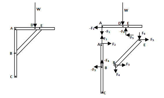
Following figure gives a basic idea of what we are going to study. The given figure is a normal diagram of a book shelf. The second figure shows the role of internal forces in maintaining the system equilibrium. Free body diagram of various components are shown. It is clear from the diagram that the forces of action and reaction between various parts are equal in magnitude and opposite in direction.
Definition of a Truss
Sometime a member may be given of a shape like:
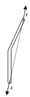 In such a case take the line the line joining their ends as the line of action of force.
Analysis of a Truss
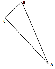
A truss needs to be stable in all ways for security reasons. Simplest stable truss ABC is shown in figure.
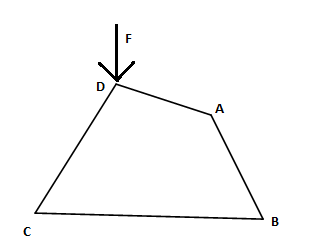
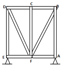
The second diagram depicts that how instable the truss structure is. The truss ABCD can easily be deformed by application of the force F. Trusses constructed by adding triangles such as arms AC and CD to the above stable truss ABC are called simple trusses. No doubt simple trusses are rigid(stable). Further it is not always necessary that rigid trusses will necessary be simple. Let m be no. of members and n be number of joints. For a truss with m
m>2n-3 excess member , statically indeterminate, more unknown than equation
Method of Joints
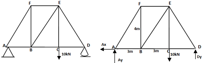
Step 1. Find the reaction at supporting pins using the force and the moment equations.
Step 2. Start with a pin, most preferably roller pin,wher there are 2 or less than two unknowns.
Step 3. Proceed in a similar way and try to find out force in different members one by one.
Step 4. Take care of while labelling forces on the members. Indicate compression and tension clearly.
Step 5. Finally produce a completely labelled diagram.
Step 6.Try to identify the zero force members. It makes the problem simple.
Above shown are the conditions of compression or tension, deceided as per the direction of force applied by the pin joints to the members.
Method of Sections
As the name suggests we need to consider an entire section instead of joints. When we need to find the force in all the members, method of joint is preferrable. For finding forces in few of the specific members method of joints is preferrable. Let us consider the same diagram as before.
We had been provided with the given system. We draw a axis aa’.
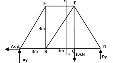
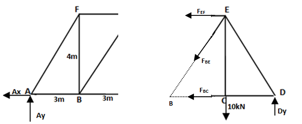
The axis should at max intersect three members. Then we separate the two sections apart. We can select any one of the part. We have just assumed he member to be in tension. We can find the reaction at supports. Now what we have done is divided the whole structure into two parts and taking into consideration various external reactions and member forces acting of one part.Suppose we have to find FEF. It is sufficient to write the equation MB =0(for equlibrium). To find FBC it is sufficient to write the equation of ME =0. Similarly we can also use the equatons Fx =0 ,Fy =0 , for the equlibrium of the section under consideration.
